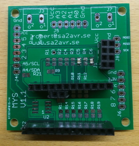
Mys 1.1 is a general purpose baseboard for use in a MySensors network.
To make it a complete sensor or gateway you also need a nrf24L01+ radio module and an arduino pro mini module.![]()
Important:
There are three ways of powering the board:
- 5-12V on connector J3.
- 5V or 3,3V on connector J7 depending on what pro mini you are using.
- through usb to serial port adapter but it has limited current.
Use only one of them at the same time!
Use right polarity!
Schematic:
Parts list:
- U1 Morex XC6206P332MR (marked 662K)
- U2 24LCxxx (not included)
- C1,C2 1uf capasistor (2x brown unmarked)
- C3,C4,C5,C6 100nf capasistor (4x brown unmarked)
- R1-R21 10×4.7K (472) 4x1K (102) 4x10K (103) 4x120k(124) Resistors included see assembly instructions.
- J1 2×4 pin female header
- J2 2 pieces 12-pin female headers + 1 piece 2-pin female header.
- J3,J7 2-pin screw terminal.
- J4 8-pin male header
- J5,J6 6-pin male header
- J8 3-pin male header
- nrf24L01+ Radio and arduino pro mini (not included)
- sensor and/or actuator (not included)
Assembly instructions:
Step 1:
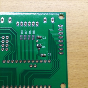
Solder C1,C2 and U1 on bottom of board if you are using a 5V arduino. If you use a 3,3V arduino you can make a jumper between Vcc and 3,3V on header J6 or bridge Vcc and 3,3V pads on U1.
Step2:
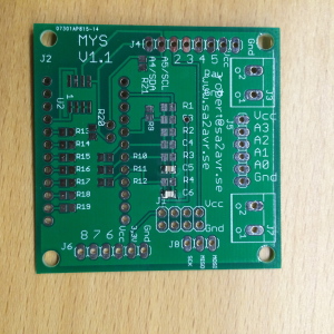
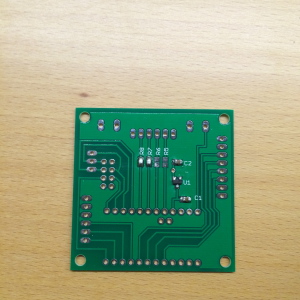
Solder all resistors on top of board that you need depending on application. R1-R4 pulldown for A0-A3. R5-R8 on bottom of board, voltage dividers for A0-A3, bridge if not used. R9-R12 pullups for A0-A3. R13-R19 pullups for D2-D8. R20-R21 pullups for A4-A5. Also solder C3-C6 if A0-A3 is used as analog inputs.
Step3:
Solder U2 if used (not included in kit).
Step 4:
Cut and solder headers J1 and J2 or solder radio and arduino directly on board.
Step 5:
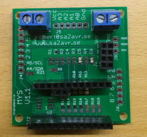
Solder J3 and J7 if used.
Step 6:
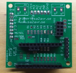
Cut and solder J4-J6 and J8 if used. They can be mounted both on top and bottom side.
Step 7:
Check for shorts between Vcc, Gnd and Raw.
Step 8:
Plug in your Arduino with a mysensors sketch and radio.
Have fun!
Tips and tricks
As there has been some questions of how to use the included resistors am I going to give some exampels:
- If you connect a 10K NTC temp sensor or LDR between gnd and A0 you may need a 10K pullup on R12 and bridge R8.
- If you want to meassure a voltage 0-24V on A1 you need to divide it with 120K on R7 and 10K R3.
- If you connect a DS18b20 temp sensor to pin 2 you need a 4,7K resistor on R13.
- If you want to use I2C you probably need 4,7K on R20 and R21.
- If you connect a indication LED between A2 and vcc you need a 1K on R6.
